The input of the main control is the opcode field (bits 31:26) of an instruction. It is referred as
Op6, where 6 is for 6 bits.
The implementation of the main control is simple.
It includes a decoder and a logic unit implementing the following logic equations:
RegDst = R-type RegWrite = ¬(sw + beq + bne + j) ExtOp = ¬(andi + ori + xori) ALUSrc = ¬(R-type + beq + bne) MemRead = lw MemtoReg = lw MemWrite = sw |

|
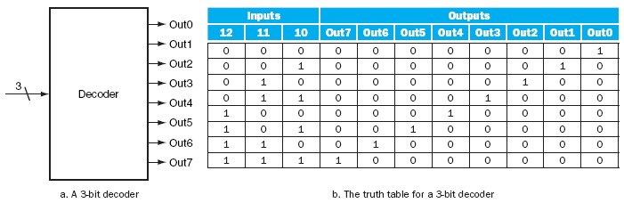
The most common type of decoder has an
n-bit input and 2n outputs, where only one output is asserted for each input combination.
This decoder translates the n-bit input into a signal that corresponds to the binary value of the n-bit input.
The outputs are thus usually numbered, say,
Out0,Out1, ...,Out2n-1
i, then Outi will be true and all other outputs will be false.
The following figure shows a 3-bit decoder and the truth table.
This decoder is called a 3-to-8 decoder since there are 3 inputs and 8 (23) outputs.
|
“There is an ancient tribal proverb I once heard in India. It says that before we can see properly we must first shed our tears to clear the way.” ― Libba Bray, The Sweet Far Thing |